LaTeX Graphics using TikZ: A Tutorial for Beginners (Part 2)—Generating TikZ Code from GeoGebra
Part 1 | Part 2 | Part 3 | Part 4 | Part 5
Author: Josh Cassidy (August 2013)
This five-part series of articles uses a combination of video and textual descriptions to teach the basics of creating LaTeX graphics using TikZ. These tutorials were first published on the original ShareLateX blog site during August 2013; consequently, today's editor interface (Overleaf) has changed considerably due to the development of ShareLaTeX and the subsequent merger of ShareLaTeX and Overleaf. However, much of the content is still relevant and teaches you some basic LaTeX—skills and expertise that will apply across all platforms.
In this video we're going to look at using GeoGebra to generate TikZ code to use in our LaTeX documents. GeoGebra is a great tool for creating and displaying mathematical diagrams. You can get a copy of GeoGebra from the GeoGebra website, www.geogebra.org.
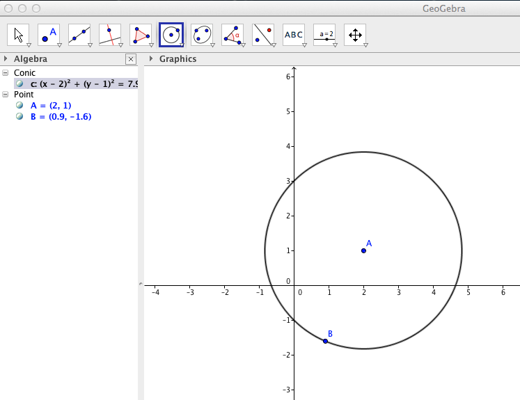
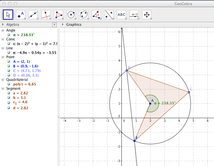
Let's start by creating a simple diagram in GeoGebra. First we'll add a circle using the Circle with Centre through Point tool:
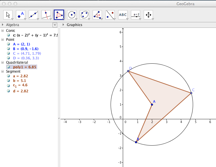
Next we'll add a polygon inside our circle using the Polygon tool:
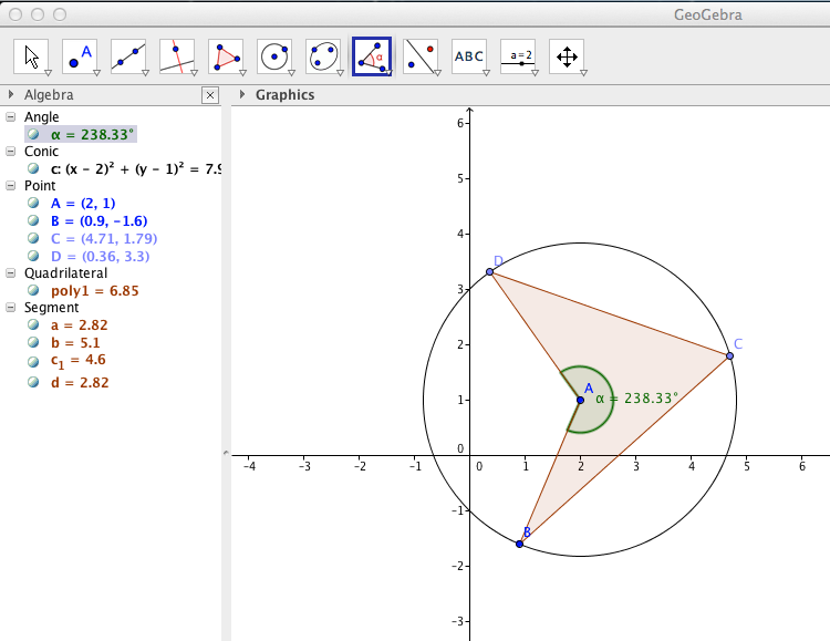
Then we'll measure an angle inside this polygon using the Angle tool:
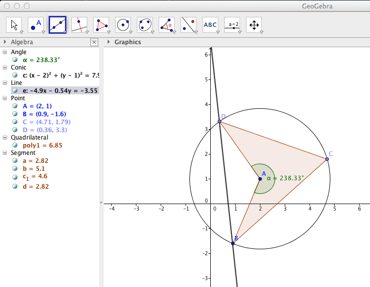
Now we'll add a straight line going through two points on the circle using the Line through Two Points tool:
We'll finish up by turning the grid on. To do this we select the Move tool, right click on the background and select the Grid option:
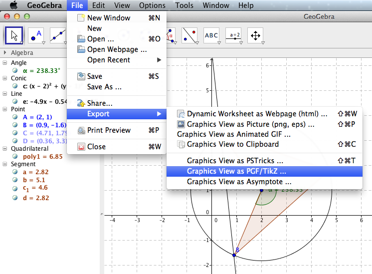
Now to export this as TikZ code we open the file menu, hover over Export and click on Graphics View as PGF/TikZ:
We then tell GeoGebra how much of the grid we want included in our tikzpicture by altering the x and y minimum and maximum points. You'll see a blue box represent this area on the grid. Next we check the format is set to LaTeX article class and then click the generate button:
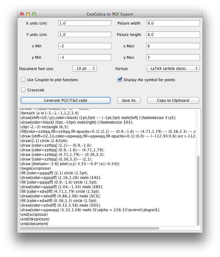
Now if we hit Copy to Clipboard we can then paste it into an empty tex file. You'll notice that it has generated a preamble where it loads up the tikz package and a TikZ library, it sets the page style to empty and it also defines a new command:
\usepackage{pgf,tikz}
\usetikzlibrary{arrows}
\pagestyle{empty}
\newcommand{\degre}{\ensuremath{^\circ}}
Then it begins the document and defines some colours before opening a tikzpicture environment:
\definecolor{qqwuqq}{rgb}{0,0.39,0}
\definecolor{zzttqq}{rgb}{0.6,0.2,0}
\definecolor{xdxdff}{rgb}{0.49,0.49,1}
\definecolor{qqqqff}{rgb}{0,0,1}
\definecolor{cqcqcq}{rgb}{0.75,0.75,0.75}
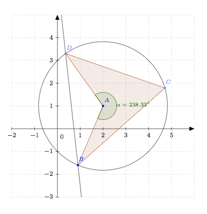
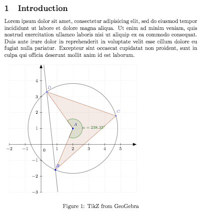
If we compile the code we'll see it appear in the document. As it's generated from TikZ code rather than an image, it's very high quality:
We could also turn the TikZ picture into a figure to give us more control over things like positioning. To do this we simply enclose the tikzpicture environment in the figure environment. We can then add a placement specifier, a caption and a label:
\begin{figure}[!h]
<tikzpicture environment>
\label{circle1}
\caption{TikZ from GeoGebra}
\end{figure}
Now if we want to include this figure in an existing document we can copy over everything in the figure environment. We also need to make sure we copy over the relevant parts of the preamble if they're not in our existing docs preamble already. Therefore we'll copy over the \usepackage command and \usetikzlibrary command as well as the \newcommand definition. Finally we also need to copy over the colour definitions.
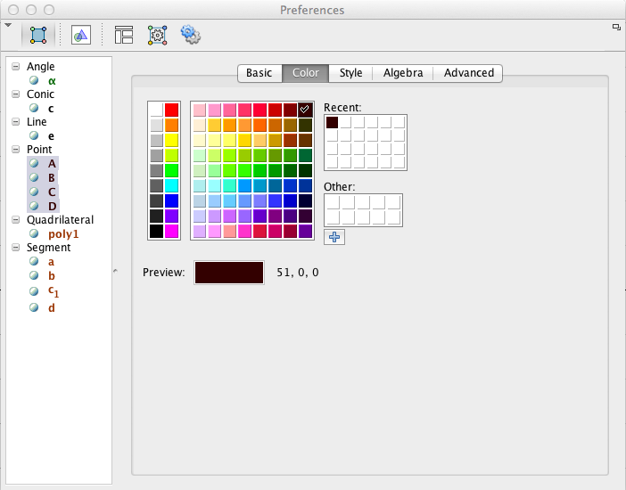
If we go back to GeoGebra we can alter the way our diagram looks by right clicking on it and changing the object properties. For example we can change colours, point styles, line styles and line thickness.
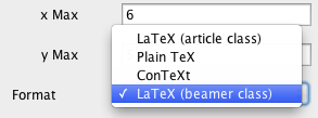
Another useful thing we can do with GoeGebra is export to Tikz in a beamer format so that we can add diagrams into presentations. To do this we export like before except we select the LaTeX (beamer class) option:
If we now copy this into a blank .tex file and compile the document you'll notice it has generated a number of slides which build up the diagram piece-by-piece:
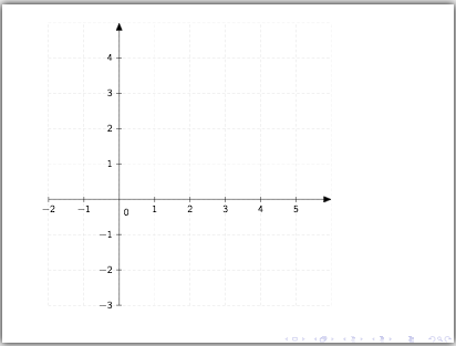
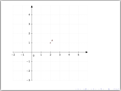
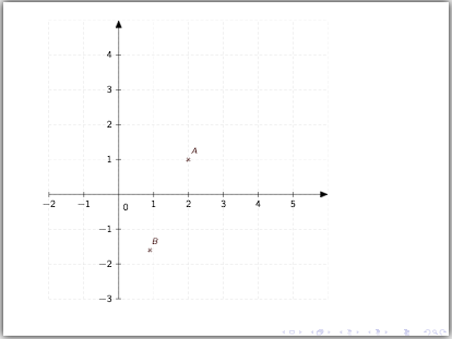
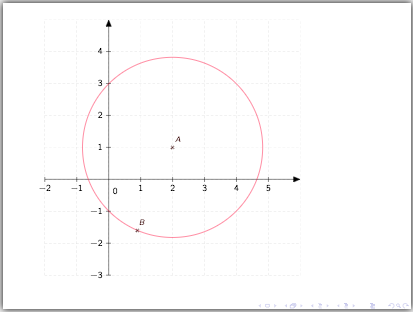
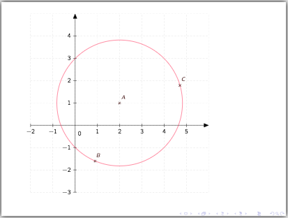
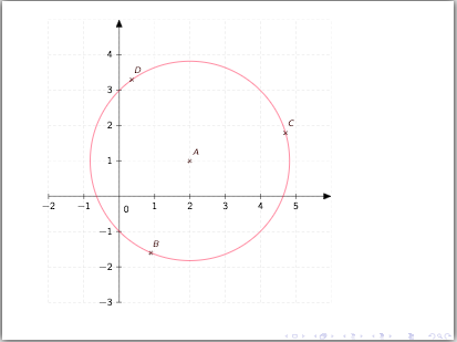
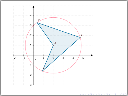
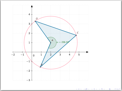
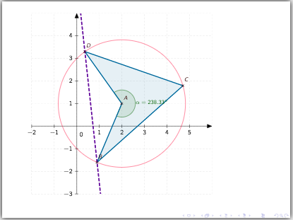
This is due to the \onslide overlay specifications that GeoGebra has automatically generated for us. For example this \onslide command tells beamer to show the circle from slide four onwards:
\onslide<4->{
  \draw [color=ffqqtt] (2,1) circle (2.82cm);
}
We can edit these overlay specifications to make the diagram come together in whatever way we want. For example we may want to make the circle appear on the same slide that point B appears. To do this we change this \onslide command from <4-> to <3-> and then, as the circle was the only item to appear on slide four, we knock the numbering of all overlay specifications above four down by one. Again if you want to add this frame into another beamer presentation you can just copy over all the relevant parts as we did with the document earlier.
This concludes our discussion on using GeoGebra to generate TikZ code. In the next post we'll look at creating flowcharts.
All articles in this series
- Part 1: Basic Drawing;
- Part 2: Generating TikZ Code from GeoGebra;
- Part 3: Creating Flowcharts;
- Part 4: Circuit Diagrams Using Circuitikz;
- Part 5: Creating Mind Maps.
Please do keep in touch with us via Facebook, Twitter or via e-mail on our contact us page.